Bidirectional Photoelectric System

Photoelectric
detectors are usually unidirectional, i.e. they are able to detect when
someone enters a particular area but not when leaves it. On the
contrary, a system able to detect movement in both directions could be
useful to control shops, rooms etc.
If installed in a shop it could allow to know if all customers entering
the premises have left them at the end of the day. Or, at home, it could
be used to switch on the light (or any other electric device) when one
enters the room and to switch off the electric device when he or she
leaves it.
Furthermore, the circuit is able to control the number of people, as it
switches off the electrical device only when the last person has left
the controlled area.


Input & Output Counter
Read Full article[...]

Fuse Box Toyota 1992 Corolla Side Kick Panel Diagram

Fuse Box Toyota 1992 Corolla Side Kick Panel Diagram - Here are new post for Fuse Box Toyota 1992 Corolla Side Kick Panel Diagram.

Fuse Box Toyota 1992 Corolla Side Kick Panel Diagram


Fuse Box Toyota 1992 Corolla Side Kick Panel Diagram

Fuse Panel Layout Diagram Parts: clutch start relay, defogger relay, power circuit braker, gauges, radio, wiper, stoplight, engine, ignition, taillight, turn signal light, cigar lighter, sun roof, ECU ignition.
Read Full article[...]

Complete Room Securty System Circuit diagram

This simple circuit is called room security system circuit. The main purpose of this circuit is to secure your room in night. You need not any security guard. When any unwanted person wants to enter your room in night then this circuit raised alarm. On the other benefit, it is always activated on load shedding. 


There are five separates parts in this circuit – regulated power supply, relay driver, door switching, alarm system and audio amplifier.
First section is regulated power supply. The output of IC 7809 is
regulated +9Volt which is converted from 9Volt unregulated power supply.
Capacitors are used for removing ripple. A full wave 9 volt transformer is connected in the input of this power section.

The second part is relay driver. Q1 transistor is used for driving relay.
When the Q1 transistor is forward bias then the relay is ON and the
total circuit gets positive voltage from ac source. In the time of load
shedding relay is deactivated and the total circuit gets power from
6Volt Battery.

The third part is door switching. When C1 capacitor’s two terminals are short, transistor Q2 is reversed
biased. So Q2 transistor is OFF. When C1 capacitor’s two terminals are
open, transistor Q2 is forward biased. So Q2 transistor is ON. For this
reason IC UM66 is ON and it
generates music which is feed another two transistors Q3 and Q4. A
speaker is connected with collector of the transistor Q4 as circuit
diagram.
Read Full article[...]

Rangkaian Power Supply for tube amplifier

Power supply for EL-34 tube is specially designed for the purposes of power supply at the push-pull amplifier with EL-34 tube as in article 35 Watt Tube Power Amplifier Push Pull before.
Power supply for EL-34 tube amplifier is made with transformers CT and 2 pieces diode as rectifier. Mechanical filters are applied in the power supply uses 3 levels. Power supply for tube power amplifier can deliver output voltages +220 VDC. Circuit details can be seen in the following figure.


The above power supply circuit has a high output voltage so that need to be considered in the manufacture and perakitanya because electricity can tesengat (stun). Power Supply For Tube Power Amplifier With Diode EL-34 was created specifically for the power amplifier tube push pull EL-34.
Read Full article[...]

150 watts power amplifier circuit

Amplifier circuit is 150 watts power amplifier circuit is quite simple.
This circuit requires only 5 pieces of transistors as the main component of reinforcement. There is no equalizer option on this amplifier circuit because it can be said of this series is very simple, so do not you compare it with that sold in the market which are usually equipped with various sound system and equalizer settings. 


But to add to your collection circuit, this circuit is fairly easy and inexpensive to make and maybe one day you may need as a weak signal booster from your electronic circuit. Or you can also make this amplifier as an amplifier of high frequency signal from the output circuit animal repellent and I guarantee the results are very satisfactory.

150 watts power amplifier circuit


Power supply required is two-polarity power supply is + - 45 volts. Maximum power that can be obtained by this amplifier circuit is around 150 watts. As the volume control you can add potensio or variable resistor 10 Kohm in series at the input. Use dispasi loudspeaker with 150 watts power. Use a heatsink on the transistor-transistor driver loudspeaker or amplifier late as Q1 and Q2.
Read Full article[...]

Stereo Amplifier with Voltage Regulators

A simple stereo audio amplifier is built around two 7905 negative-voltage regulators (IC1 and IC2) and a few discrete components. The circuit will also work with other 79XX regulators if appropriate power supply is used. Regulator IC 7905 works as an amplifier for the voltages applied to common pin2 (Ground or GND). Also check the LM317 audio amplifier, another interesting circuit.
The minimal voltage drop over the standard 7905 is around 2V and it depends on the output current. Feedback resistors in the IC set the gain of the channel internally. The amplifier is a class-A audio amplifier. The minimal applicable value of R3 for the regulator 7905 is 8.2 to 10 ohms per 5W.

1W Stereo Amplifier with Voltage Regulators Circuit Diagram

A simple Stereo Amplifier with Voltage Regulators

If the required output current for LS1 is below 100 mA, the value of resistor R3 can be 33 to 51 ohms per watt. The circuit works with any load resistance (R3 in parallel with LS1 as the load) under the condition that the regulator is not overloaded with current and power dissipation. However, it is preferable to use a loudspeaker with a high resistance (8 ohms, 16 ohms or more). The amplifier works well with low-impedance headphones having a resistance of 24 to 32 ohms. The voltage difference between the ground pin of 7905 and the output pin is fixed internally.
S2 is the on/off switch. Switch S1 is for mono/stereo selection. When switch S1 is closed, the amplifier works as a two-way mono amplifier. If S1 is open, the amplifier works as a stereo amplifier. If no input signal is applied, the DC voltage on the output of the regulator 7905 should be around –5V, which depends to some extent on the value of VR1. The maximum output current of 7905 can be up to 1A and the maximum power dissipation is up to 15W. Mount the regulator IC 7905 on a heat-sink with thermal resistance below 15°C/W.
Source:  http://www.ecircuitslab.com/2012/08/a-simple-stereo-amplifier-with-voltage.html
Read Full article[...]

1985 Ford F250 Pickup Wiring Diagram

1985 Ford F250 Pickup Wiring Diagram
(click for full size image)

The Part of 1985 Ford F250 Pickup Wiring Diagram to direct, switch, direct.light, wht blk, blk, brn, park light, right headlight, red/blk, blk, lt grn/blk, hi beam, ro horn switch, yel/grn, yel/grn, horns, grn/blk, hi beam, blk, red/blk, left headlight, to direct switch, grn/wht, direct.light, wht blu, blk. brn, park light, left marker light, blk, brn, right marker light, beam select switch, lo hi, red /yel, to light switch grn/blk, to high beam indicator, carb solenoid, red/yel, throttle actuator, tan/ wht, red/yel, blk, red grn, brn, to headlight switch, brn, battery, red, blk/yel, fusible link, blk?orb, to marker light relay, carburator stepper motor, coolant temperature sensor, noise filter, ignition coil, wht/lt blu, grn/yel.
Read Full article[...]

Connection Tester


A low resistance ( 0.25 - 4 ohm) continuity tester for checking soldered joints and connections.


This simple circuit uses a 741 op-amp in differential mode as a continuity tester. The voltage difference between the non-inverting and inverting inputs is amplified by the full open loop gain of the op-amp. Ignore the 470k and the 10k control for the moment, and look at the input of the op-amp. If the resistors were perfectly matched, then the voltage difference would be zero and output zero. However the use of the 470k and 10k control allows a small potential difference to be applied across the op-amp inputs and upset the balance of the circuit. This is amplified causing the op-amp output to swing to full supply voltage and light the LEDs.

Connection Tester Circuit DiagramSetting Up and Testing:

The probes should first be connected to a resistor of value between 0.22 ohm and 4ohm. The control is adjusted until the LEDs just light with the resistance across the probes. The resistor should then be removed and probes short circuited, the LEDs should go out. As the low resistance value is extremely low, it is important that the probes, (whether crocodile clips or needles etc) be kept clean, otherwise dirt can increase contact resistance and cause the circuit to mis-operate. The circuit should also work with a MOSFET type op-amp such as CA3130, CA3140, and JFET types, e.g. LF351. If the lEDs will not extinguish then a 10k preset should be wired across the offset null terminals, pins 1 and 5, the wiper of the control being connected to the negative battery terminal.
Read Full article[...]

2000 Yamaha Gp1200 Starter Motor Exploded Diagram Parts

Auto Wiring Diagrams on Infiniti Qx56 Auto Cruise Control Wiring And System Circuit Diagram
Infiniti Qx56 Auto Cruise Control Wiring And System Circuit Diagram.


Auto Wiring Diagrams on Fuel Pump Relay Wiring Diagram
Fuel Pump Relay Wiring Diagram.


Auto Wiring Diagrams on Esteem Cooling Fan Circuit And Wiring Diagram   Circuit Schematic
Esteem Cooling Fan Circuit And Wiring Diagram Circuit Schematic.


Auto Wiring Diagrams on Wiring Diagram Here     Free Download Pdf File   Source  Www
Wiring Diagram Here Free Download Pdf File Source Www.


Auto Wiring Diagrams on Chevrolet Monte Carlo Wiring Diagram And Electrical Schematics  1997
Chevrolet Monte Carlo Wiring Diagram And Electrical Schematics 1997.


Auto Wiring Diagrams on Yaris Blower Motor Circuit And Wiring Diagram   Circuit Schematic
Yaris Blower Motor Circuit And Wiring Diagram Circuit Schematic.


Auto Wiring Diagrams on Ru   Find Also Other Toyota Wiring Diagram You Might Be Looking For
Ru Find Also Other Toyota Wiring Diagram You Might Be Looking For.


Auto Wiring Diagrams on Isuzu Trooper Starting System Circuit And Wiring Diagram  98     02
Isuzu Trooper Starting System Circuit And Wiring Diagram 98 02.


Auto Wiring Diagrams on 2000 Yamaha Gp1200 Starter Motor Exploded Diagram And Parts
2000 Yamaha Gp1200 Starter Motor Exploded Diagram And Parts.


Auto Wiring Diagrams on Toyota Hiace Wiring Diagram And Electrical System  2006    Circuit
Toyota Hiace Wiring Diagram And Electrical System 2006 Circuit.


Read Full article[...]

Opto-Thermo Control Relay Switch with IC 741


Circuit Opto-Thermo Control Relay Switch with IC 741

This be Electronic switch circuit is onely. Which work with the light
and the temperature. I begs for to call that Opto-Thermo Control Relay
Switch with IC 741. By have work various instructions very much. And
have onely observations be I uses IC 741 then can insist that. Must
easy and economize. For electric appliances supervision as a result
command change , Relay there.
Read Full article[...]

Cross Linking With Two Patch Cables

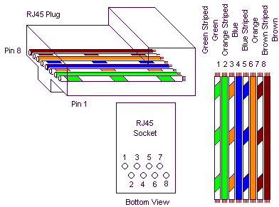
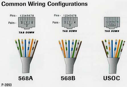
In networks, the supremacy of coax cable is a thing of the past. Nowadays, Ethernet connections are made using UTP cables. The BNC plug has yielded to the 8-way RJ45 plug. Previously, coax cables were daisy-chained from computer to computer and terminated at the two ends using 50-_ resistors, but modern networks use central ‘socket boxes’ (switches and/or hubs) to interconnect everything. The connections between the hubs and the computers are made using patch cables having the same sequence of leads in the RJ45 connectors at each end. For making a direct connection between two computers without using a hub or switch, a ‘crossover cable’ is used.

Cross-Linking With Two Patch Cables
Cross-Linking With Two Patch CablesSuch a cable has the leads cross-linked in order to allow the two computers to directly communicate with each other. If there are problems with the network, it can be handy to be able to directly interconnect twocomputers, or directly connect a computer to a cable or ADSL modem without using a hub or switch. A long crossover cable is not always available, and shoving around computers is not an attractive alternative. Consequently, we can use a dual RJ45 wall outlet box to construct an adapter, which can be used to interconnect the two patch cables coming from the equipment in question. This outlet box must be wired to create a cross-linked connection. This is done by making the following internal connections:
  • 1 → 3
  • 2 → 6
  • 3 → 1
  • 4 → 4
  • 5 → 5
  • 6 → 2
  • 7 → 7
  • 8 → 8
 
Source by : streampowers
Read Full article[...]

Mini High Voltage Generator

Here’s a project that could be useful this summer on the beach, to stop anyone touching your things left on your beach towel while you’ve gone swimming; you might equally well use it at the office or workshop when you go back to work. In a very small space, and powered by simple primary cells or rechargeable batteries, the proposed circuit generates a low-energy, high voltage of the order of around 200 to 400 V, harmless to humans, of course, but still able to give a quite nasty ‘poke’ to anyone who touches it.  Quite apart from this practical aspect, this project will also prove instructional for younger hobbyists, enabling them to discover a circuit that all the ‘oldies’ who’ve worked in radio, and having enjoyed valve technology in particular, are bound to be familiar with. As the circuit diagram shows, the project is extremely simple, as it contains only a single active element, and then it’s only a fairly ordinary transistor. As shown here, it operates as a low-frequency oscillator, making it possible to convert the battery’s DC voltage into an AC voltage that can be stepped up via the transformer.  

Using a centre-tapped transformer as here makes it possible to build a ‘Hartley’ oscillator around transistor T1, which as we have indicated above was used a great deal in radio in that distant era when valves reigned supreme and these was no sign of silicon taking over and turning most electronics into ‘solid state’. The ‘Hartley’ is one of a number of L-C oscillator designs that made it to eternal fame and was named after its invertor, Ralph V.L Hartley (1888-1970). For such an oscillator to work and produce a proper sinewave output, the position of the intermediate tap on the winding used had to be carefully chosen to ensure the proper step-down (voltage reduction) ratio.  Here the step-down is obtained inductively. Here, optimum inductive tapping is not possible since we are using a standard, off-the-shelf transformer. However we’re in luck — as its position in the centre of the winding creates too much feedback, it ensures that the oscillator will always start reliably. 

However, the excess feedback means that it doesn’t generate sinewaves; indeed, far from it. But that’s not important for this sort of application, and the transformer copes very well with it.  The output voltage may be used directly, via the two current-limiting resistors R2 an R3, which must not under any circum-stances be omitted or modified, as they are what make the circuit safe. You will then get around 200 V peak-to-peak, which is already quite unpleasant to touch. But you can also use a voltage doubler, shown at the bottom right of the figure, which will then produce around 300 V, even more unpleasant to touch. Here too of course, the resistors, now know as R4 and R5, must always be present. The circuit only consumes around a few tens of mA, regardless of whether it is ‘warding off’ someone or not! If you have to use it for long periods, we would however recommend powering it from AAA size Ni-MH batteries in groups of ten in a suitable holder, in order not to ruin you buying dry batteries.

Circuit diagram:
mini-high-voltage-generator-circuit diagram
Mini High-Voltage Generator Circuit Diagram
Warning!
If you build the version without the voltage doubler and measure the output voltage with your multimeter, you’ll see a lower value than stated. This is due to the fact that the waveform is a long way from being a sinewave, and multimeters have trouble interpreting its RMS (root-mean-square) value. However, if you have access to an oscilloscope capable of handling a few hundred volts on its input, you’ll be able to see the true values as stated. If you’re still not convinced, all you need do is touch the output terminals... 

To use this project to protect the handle of your beach bag or your attachecase, for example, all you need do is fix to this two small metallic areas, quite close together, each connected to one output terminal of the circuit. Arrange them in such a way that unwanted hands are bound to touch both of them together; the result is guaranteed! Just take care to avoid getting caught in your own trap when you take your bag to turn the circuit off!
..::: Do not built this circuit if your not an EXPERT :::..

Streampowers
Read Full article[...]

Video Switch for Intercom System

Nowadays a lot of intercom units are  equipped with video cameras so that you can  see as well as hear who is at the door. Unfortunately, the camera lens is perfectly placed  to serve as a sort of support point for people  during the conversation, with the result that  there’s hardly anything left see in the video  imagery.  One way to solve this problem is to install two cameras on the street side instead only  one, preferably some distance apart. If you  display the imagery from the two cameras  alternately, then at least half of the time you  will be able to see what is happening in front  of the door. Thanks to the video switch module described  here, which should be installed on the street  side not too far away from the two cameras,  you need only one monitor inside the house and you don’t need to install any additional video cables.
 
Video Switch for Intercom System Circuit diagram:
Video Switch for Intercom System-Circuit-Diagram


Along with a video switch, the circuit includes  a video amplifier that has been used with  good results in many other Elektor projects,  which allows the brightness and the contrast  to be adjusted separately. This amplifier is  included because the distance between the  street and the house may be rather large, so it is helpful to be able to compensate for cable attenuation in this manner.  The switch stage is built around the well  known 4060 IC, in which switches IC2a and  IC2d alternately pass one of the two signals to  the output. They are driven by switches IC2b and IC2c, which generate control signals that  are 180 degrees out of phase. The switching rate for the video signals is  determined by a clock signal from an ‘old  standby’ 555 IC, which causes the signals to  swap every 2 seconds with the specified com ponent values.
 
Naturally, this circuit can also used in many other situations, such as where two cameras are needed for surveillance but only one video cable is available.
 
Author :Jacob Gestman Geradts - Copyright : Elektor

Source :  http://www.ecircuitslab.com/2012/02/video-switch-for-intercom-system.html


Read Full article[...]

Wireless receiver microphone circuit

Just as in the transmitter circuit, the series of FM Wireless Microphone Receiver Hi Fi also uses an FM audio receiver module. Module used in the circuit FM Wireless Microphone Receiver Hi Fi has a good feture, namely audio FM receiver module has a function that is able to muffle the noise squel. Audio FM receiver module that is used in FM Wireless Microphone Receiver Hi Fi also does not require a lot of supporting components in the RF signal reception.


receiver microphone circuit


Part Series FM Wireless Microphone Receiver Hi Fi
To provide an output signal according to the needs and stable output signal audio FM receiver module on FM Wireless Microphone Receiver Hi Fi is fed to an audio preamplifier which uses IC TLC272. Levelk audio signal set by potentiometer P1. As a voltage regulator for power source circuit FM Wireless Microphone Receiver Hi Fi LM7805 regulator IC is used.

Read Full article[...]

How to repair nokia 3110c charger not support

Here is tips how to repair nokia 3110c with charger not support problem

Charger not support
1. Check batteray and charger first, replace if needed
2. If the problem not solved, check R2070, replace R2070 if needed. ( schematic as shown)

Read Full article[...]

Programming The Propeller IC

Parallax, well known for its successful Basic Stamp IC, has recently introduced the Propeller: a new microcontroller with a certain difference. It packs no less than eight 32-bit processors (referred to as COGs in Propeller jargon) into a single package with only 40 pins. That design takes genuine simultaneous multiprocessing possible, and the sophisticated internal structure of the device makes it relatively easy to implement video and signal-processing applications. The Propeller can be programmed in assembly language or the high-level Spin language. The processor and the programming tools were developed entirely in-house by Parallax, with the hardware being designed from scratch starting at the transistor level.

Circuit diagram:

programming-the-propeller-ic-circuit-diagramw

Programming The Propeller IC Circuit Diagram

The basic idea behind that was to avoid becoming involved in all sorts of patent disputes with other manufacturers. The result is astounding, and for software developers it certainly requires a change in mental gears. As is customary with modern microprocessors, the Propeller has a simple serial programming interface. The developer’s toolkit from Parallax has a modern USB port for that purpose, but a reasonably simple alternative (illustrated here) is also possible for anyone who prefers to work with the familiar RS232 port. Don’t forget that the Propeller works with a 3.3-V supply voltage.

Copyright: Elektor Electronics

Read Full article[...]

Class A headphone amplifier

Class A headphone amplifier
Read Full article[...]

USB Powered Audio Power Amplifier Circuit Diagram

This circuit of multimedia speakers for PCs has single-chip-based design, low-voltage power supply, compatibility with USB power, easy heat-sinking, low cost, high flexibility and wide temperature tolerance. At the heart of the circuit is IC TDA2822M. This IC is, in fact, mono-lithic type in 8-lead mini DIP package. It is intended for use as a dual audio power amplifier in battery-powered sound players. Specifications of TDA2822M are low quiescent current, low crossover distortion, supply voltage down to 1.8 volts and minimum output power of around 450 mW/channel with 4-ohm loudspeaker at 5V DC supply input.

An ideal power amplifier can be simply defined as a circuit that can deliver audio power into external loads without generating significant signal distortion and without consuming excessive quiescent current. This circuit is powered by 5V DC supply available from the USB port of the PC. When power switch S1 is flipped to ‘on’ position, 5V power supply is extended to the circuit and power-indicator red LED1 lights up instantly. Resistor R1 is a current surge limiter and capacitors C1 and C4 act as buffers. Working of the circuit is simple. Audio signals from the PC audio socket/headphone socket are fed to the amplifier circuit through components R2 and C2 (left channel), and R3 and C3 (right channel).

Circuit diagram:

USB Powered Audio Power Amplifier Circuit Diagram

USB Powered Audio Power Amplifier Circuit Diagram

Potmeter VR1 works as the volume controller for left (L) channel and potmeter VR2 works for right (R) channel. Pin 7 of TDA2822M receives the left-channel sound signals and pin 6 receives the right-channel signals through VR1 and VR2, respectively. Ampl i f ied signals for driving the left and right loudspeakers are available at pins 1 and 3 of IC1, respectively. Components R5 and C8, and R6 and C10 form the traditional zobel network. Assemble the circuit on a medium-size, general-purpose PCB and enclose in a suitable cabinet. It is advisable to use a socket for IC TDA2822M. The external connections should be made using suitably screened wires for better result.

Author: T.K. Hareendran - Copyright: EFY Mag

Read Full article[...]

led light running arrows showing the position circuit and explanation


This
is a led light running circuit with a number generated from IC
CD4093, CD4520 and CD4094.This circuit can adjust the speed with
resistors R1.When entering the power supply to the circuit IC1. A nand
gate IC Oscillator generator circuit is connected to the input signal
generator to pin 1 of IC2 and pin 3 of the IC3.When receiving the
signal from IC1 IC2 will serve up the signal from the logic into the
binary.Then sent to the pin 5 and pin 6 of IC1, IC1, which will process
a nand gate.The IC3 is the signal from IC1 to processing and export
of pin 4, 5, 6 and 7.Then entered into the base of the transistor pins
Q1-Q4.Any work on the transistor connected to the LED pin collector
will glow out come.For the format of the 17 LED Lights, arranged as a
form of directional arrows.
source: www.eleccircuit.com
Read Full article[...]

Cat and Dog Repeller

Nowadays, just about every house has an outside lamp with a motion sensor. Such a device eliminates the need to feel your way to the front door, and it apparently also scares away intruders. The only problem is that free-running dogs and cats in the neighborhood have little regard for such lamps and continue to deposit their excrement in the garden, once they have found a habitual location there for this purpose. This gave rise to the idea of connecting a sort of siren in parallel with the outside lamp to clearly advise dogs and cats that they are not welcome.

Naturally, it would be nice to avoid startling the entire neighborhood with this alarm signal. Here we can take advantage of the fact that dogs and cats have a significantly better sense of hearing than people. Not only are their ears more sensitive, they can also perceive significantly higher frequencies. With people, the upper limit is around 18 kHz, but dogs and cats can hear frequencies in excess of 20 kHz. We can take advantage of this by building a siren that emits a frequency just above 20 kHz.

Cat and Dog Repeller Circuit diagram :
Cat and Dog Repeller Circuit Diagram


This will scare off dogs and cats, but people will simply not hear it. All we need for this is an oscillator with an amplifier stage and a tweeter that can reproduce such high frequencies, such as a piezoelectric tweeter. The schematic diagram shows how easily this can be implemented. The power supply for the entire circuit is formed by the components up to and including C2. The 230-V leads are connected in parallel with the motion-sensor lamp. C1 and R1 provide capacitive coupling to reduce the 230 V to an acceptable voltage. 

A DC voltage of approximately 9.1 V is generated from this voltage using a bridge rectifier and D1, filtered and buffered by C2. The oscillator is built around R3, C3 and IC1a.The frequency of this oscillator is rather dependent on the specific characteristics of IC1, so the values shown here should be regarded as guidelines. If the oscillator frequency is too high, it can be reduced by increasing the value of R3 and/or C3.

If the frequency is too low (which means that the siren tone it is audible), the value of R3 and/or C3 should be increased. The square-wave signal from the oscillator is applied to the input of an H bridge composed of several Schmitt triggers in combination with the final output stages (T1–T4). This approach causes the peak-to-peak value of the square wave signal to be twice the supply voltage. As a result, a respectable 18 V is obtained across the piezoelectric tweeter, which is sufficient to produce a quite loud whistle tone. When building the circuit, you should bear in mind that it is directly powered from 230 V and not electrically isolated from the mains network.

It is thus necessary to avoid contact with all of the components when the circuit is in use. In practice, this means that the circuit must be fitted into a well-insulated, waterproof box. If you want to test the circuit, it is a good idea to first discharge C1 using a resistor, since it can hold a dangerous charge. You must also ensure that components F1, C1, R1 and B1 all have a mutual insulation separation of at least 6 mm!

Source : www.ecircuitslab.com/2011/05/cat-and-dog-repeller.html
Read Full article[...]

Great Brands for Good Prices on Auto Sound Systems

If you are one of the many people across the country considering a new auto sound system, there is a great deal of good news. First of all, it is very possible to find a good bargain on a nice sound system for your car, truck, or SUV if you are willing to shop online and install the system yourself. The problem often lies not in the cost of the system but the price of the installation. However, the cost of installation is well worth the dollar amount for many of us who really have no clue what to do as far as a project of that scope goes. I for one am among the electronically challenged and not really willing to risk my dash board for an experiment in frustration and failed electronics.

That being said, there are many who are either perfectly and wonderfully capable of installing a nice auto sound system or are fortunate enough to know someone or someone who knows someone who is. For you, finding a great bargain online is probably the best way to go-provided youve actually been in the shop and heard the sound quality of the particular system you are considering. I would never recommend buying a system youve never heard in action no matter how great of a bargain you think you are getting.

Ive found that some of these systems are not even as good as the minimal factory installed systems that come standard in most cars, trucks, or SUVs on the road today. You do not want to pay money and spend time and effort for the installation of a sound system that isnt at least better than the one you currently have.

There are times when you do not have to go with top of the line or well known brands in order to have a great sound or auto sound system. But there are some well-known, good quality makers of sound systems that do not cost a fortune. You can find some very nice sound systems that are not exactly top of the line but also offer great quality sound and excellent features (particularly when compared to factory installed sound systems).


If youre looking for a very nice auto sound system you can find some good ones by popular brands for well under $300. They have some that are even less expensive but those in the $300 range generally offer a little boost in quality from those that can be found at lower prices. Of course, this isnt always the case and you will occasionally find some excellent systems at even lower prices than this. You and you alone can tell if the system you choose is one that you will be happy with.


The thing to remember is to listen to the sounds of the systems then make your decision and compare prices. Alpine, Kenwood, and JVC all have excellent auto sound systems in a wide variety of price ranges. There are times with these systems that paying a little extra is worth it. If you are satisfied with the quality of a less expensive sound system however, there is no real reason why you should purchase a more expensive system. You are the one who will be riding in your car, truck, or SUV and it is only important what you think of the system you select.


Read Full article[...]

Basic Components for a Home Theater

Many people never bother looking into purchasing a home theater through sheer fear of the decisions that may need to be made in the process. Many among these aren’t even sure of exactly which components are included in a home theater or which ones are needed in order to create an effective and entertaining home theater. For this reason, many people simply do not bother going through the process of looking at their options when it comes to these wonderful systems on the market today much less ever bother actually purchasing one.

Basic Components for a Home Theater
If you are one of the many who has experienced some degree of confusion when it comes to the individual parts and pieces that are included in a home theater system and what they do, hopefully you will gain a better understanding once you’ve finished reading. The first thing to understand is that there are varying degrees when it comes to home theaters. The following components are the makings of a very basic home theater that will provide excellent functionality. They are not however inclusive of every possible piece or part that could make up a home theater system.

Speaker Setup
Speaker Setup
Off to the basics, the first thing you’ll need when creating a home theater for your family to enjoy is a television. It might seem a little too obvious to some but I have yet to find a box kit that includes a television—mainly because the choice of screen is for many the most personal aspect of selecting a home theater. There are essentially three choices in today’s television market: front projector, rear projector, and plasma. There are variations within each of these and the prices fall anywhere from modest to quite costly. This is the component that most home theater owners spend the most time contemplating and it affects the types of components that will be most effective later on in terms of things such as high definition and other choices you can make.

A receiver is another important component. You will probably have a DVD player or recorder of some sort as part of your system; you may have a Tivo and cable box or satellite and will probably have speakers of some sort for your system. The receiver is the box you plug them all into—it receives all of this inputs and correlates it so to speak. This is the ultimate traffic director when it comes to your home theater and I suggest you spend a good portion of your home theater budget making sure that this is a good quality part.

Speakers are where your sound will flow. One of the best things to me about a home theater is the ability to experience surround sound very similar to what I experience in theaters while having the ability to put my feet up or snuggle under blankets (which simply can’t be achieved in a theater). Speakers come in all shapes and sizes and are also quite personal for some consumers while give and take for others. You can purchase these are part of a kit in order to make the selection process easier.

Finally, you have your DVD player or recorder. If high definition is important to you, you now have that option. If your television isn’t HD ready or capable, I’d pass and go for an older (less expensive) model of DVD player until something more up-to-date is called for. These items are a great start for any home theater and you can build, expand, and upgrade over time for an even better system. Enjoy!

PPPPP

599

Related Circuit : Make 5.1 channel amplifier and speaker setup
Read Full article[...]

Mini High Voltage Generator

Here’s a project that could be useful this summer on the beach, to stop anyone touching your things left on your beach towel while you’ve gone swimming; you might equally well use it at the office or workshop when you go back to work. In a very small space, and powered by simple primary cells or rechargeable batteries, the proposed circuit generates a low-energy, high voltage of the order of around 200 to 400 V, harmless to humans, of course, but still able to give a quite nasty ‘poke’ to anyone who touches it.

Quite apart from this practical aspect, this project will also prove instructional for younger hobbyists, enabling them to discover a circuit that all the ‘oldies’ who’ve worked in radio, and having enjoyed valve technology in particular, are bound to be familiar with. As the circuit diagram shows, the project is extremely simple, as it contains only a single active element, and then it’s only a fairly ordinary transistor. As shown here, it operates as a low-frequency oscillator, making it possible to convert the battery’s DC voltage into an AC voltage that can be stepped up via the transformer.

Using a centre-tapped transformer as here makes it possible to build a ‘Hartley’ oscillator around transistor T1, which as we have indicated above was used a great deal in radio in that distant era when valves reigned supreme and these was no sign of silicon taking over and turning most electronics into ‘solid state’. The ‘Hartley’ is one of a number of L-C oscillator designs that made it to eternal fame and was named after its invertor, Ralph V.L Hartley (1888-1970). For such an oscillator to work and produce a proper sinewave output, the position of the intermediate tap on the winding used had to be carefully chosen to ensure the proper step-down (voltage reduction) ratio.

Here the step-down is obtained inductively. Here, optimum inductive tapping is not possible since we are using a standard, off-the-shelf transformer. However we’re in luck — as its position in the centre of the winding creates too much feedback, it ensures that the oscillator will always start reliably. However, the excess feedback means that it doesn’t generate sinewaves; indeed, far from it. But that’s not important for this sort of application, and the transformer copes very well with it.

The output voltage may be used directly, via the two current-limiting resistors R2 an R3, which must not under any circum-stances be omitted or modified, as they are what make the circuit safe. You will then get around 200 V peak-to-peak, which is already quite unpleasant to touch. But you can also use a voltage doubler, shown at the bottom right of the figure, which will then produce around 300 V, even more unpleasant to touch. Here too of course, the resistors, now know as R4 and R5, must always be present. The circuit only consumes around a few tens of mA, regardless of whether it is ‘warding off’ someone or not! If you have to use it for long periods, we would however recommend powering it from AAA size Ni-MH batteries in groups of ten in a suitable holder, in order not to ruin you buying dry batteries.

Circuit diagram:

mini high-voltage generator circuit schematic

Mini High-Voltage Generator Circuit Diagram


Warning!

If you build the version without the voltage doubler and measure the output voltage with your multimeter, you’ll see a lower value than stated. This is due to the fact that the waveform is a long way from being a sinewave, and multimeters have trouble interpreting its RMS (root-mean-square) value. However, if you have access to an oscilloscope capable of handling a few hundred volts on its input, you’ll be able to see the true values as stated. If you’re still not convinced, all you need do is touch the output terminals...


To use this project to protect the handle of your beach bag or your attachecase, for example, all you need do is fix to this two small metallic areas, quite close together, each connected to one output terminal of the circuit. Arrange them in such a way that unwanted hands are bound to touch both of them together; the result is guaranteed! Just take care to avoid getting caught in your own trap when you take your bag to turn the circuit off!


..::: Do not built this circuit if your not an EXPERT :::..

Elektor Electronics 2008

Read Full article[...]

1997 Honda Civic schematic Wiring Diagram

1997 Honda Civic schematic Wiring Diagram. This is the wiring diagram for your 1997 Honda Civic. There are various of diagrams that you can find on this pdf file such as schematic diagram of Honda Civic 1997 including Air Conditioning System, Anti-Lock Brakes Circuit, Anti-Theft System, Computer Data Lines, Cooling Fan, Cruise Control System, Defoggers, Engine Performance Circuit, Exterior Lights, Ground Distribution, Headlights, Horn, Courtesy Lamp Circuit, Power Antenna, Power Distribution Circuit, Power Door Lock and Power Mirror Diagram, Power Seats, Shift Interlocks System, Starting and Charging Circuit, etc

Download: 1997 Honda Civic Wiring Diagram
Read Full article[...]

Super Boost USB Charger Circuit

Read Full article[...]

555 TLC555 Relay Driver Circuit

Many integrated circuits have undocumented features or abilities. This is one of them. The TLC555 output (pin 3) can sink a 100mA load to 1.28V. The open drain transistor reset (pin 7) can sink 100mA to 1V. Tying both lines together is permissible because they are logically the same polarity and this potentially doubles the sink current ability to 200mA. This is ideal for driving my 133mA relay coil.
The input also has the undocumented, but better known, feature of a Schmitt trigger that provides positive switching.


555 Relay Driver Schematic

TLC555 Relay Driver Schematic
Protoboard setup

Output current rating (pin 3): TLC555 vs. NE555
(Vcc = 15V)TLC555NE555
Source current10mA200mA
Source mode saturation voltageVcc-0.8VVcc-2.5V
Sink current100mA200mA
Sink mode saturation voltage1.28V2.5V
While it can be seen that the NE555 has the higher current rating, its saturation voltage is grossly inferior and this is a detriment in driving loads without excessive voltage drop. Also it can be seen that the TLC555 is much like TTL in that its sourcing ability is far less than its sinking ability. However for driving a relay, we are interested only in current sinking properties.
Relay out of my junk box
12V Contactor
This is a 40A automotive relay (contactor) that I selected for this application. Since its coil current exceeds the TLC555 output sink current rating, it is a good candidate. Manufacturer or part number is unknown.
  • Contact rating: 40A (from memory)
  • Coil resistance: 90Ω cold
  • Coil current: 133mA
  • Coil power: 1.6W
  • Coil voltage: 12V
  • Pickup voltage: 4.8V cold
  • Dropout voltage: 2.1V cold
  • Operate time: 4.5mS
What is the difference between a relay and a contactor? There is no clear difference other than perhaps current rating and/or application—to me, relays are anything from signal devices to approx 20A. Anything rated at 40A or larger, or is used in power applications is a contactor.
Schmitt trigger input
The trigger input (pin 2) and the threshold input (pin 6) pins are tied together—this is commonly done. With a 12V supply, the upper threshold is 8V and the lower is 4V. The two voltage levels, being far apart, make a great Schmitt trigger. This may be driven directly by 4000series CMOS logic that is also powered via 12V.
To make it compatible with TTL logic levels, simply add the two resistors that are shown in the schematic. This loads down the internal divider to a lower voltage. The calculated levels are approx. 1.4 and 2.8V respectively.
Testing the performance
  • Output saturation voltage:
    • 0.617V @ 133mA
    • 1.043V @ 200mA
  • TTL high level threshold: 3.0V
  • TTL low level threshold: 1.6V
How about the bipolar 555 and other variants?
The standard 555 saturates poorly (2.5V) at 200mA and its reset line (pin 7) is not specified above 15mA, so it is not recommended. The intersil 7555 is a very low power device, so that is not recommended either.
For the future
  • Assorted relay driver circuits
  • 555 Voltage doubler relay driver circuit
  • Relay economy circuits
555 datasheet
Read Full article[...]

Wiring Diagramgroup Pictureimage Keywordpictures

Wiring Diagram on Cat5 Av Matrix Switches  Cat5 Audio Video Matrix Switch Solutions
Cat5 Av Matrix Switches Cat5 Audio Video Matrix Switch Solutions.


Wiring Diagram on Cat 5 Wiring Diagram
Cat 5 Wiring Diagram.


Wiring Diagram on Diagram Of Correct Color Alignment For Making Cat5e Network Cable
Diagram Of Correct Color Alignment For Making Cat5e Network Cable.


Wiring Diagram on Cat 5 Wiring Diagram For Home Networks  Security Systems And Phone
Cat 5 Wiring Diagram For Home Networks Security Systems And Phone.


Wiring Diagram on Terminating Wall Plates   Structured Home Wiring
Terminating Wall Plates Structured Home Wiring.


Wiring Diagram on Cat 5 Rj 45 Wire Diagrams
Cat 5 Rj 45 Wire Diagrams.


Wiring Diagram on Pin T568a Color T568b Color 1 Green Stripe Orange Stripe 2 Green
Pin T568a Color T568b Color 1 Green Stripe Orange Stripe 2 Green.


Wiring Diagram on Gefen Component Audio Cat5 Distribution Amplifier Wiring Diagram
Gefen Component Audio Cat5 Distribution Amplifier Wiring Diagram.


Wiring Diagram on Bt Cat5 P1 Midspan Injector Kit With 48vdc   48 Watt Power Supply   Bt
Bt Cat5 P1 Midspan Injector Kit With 48vdc 48 Watt Power Supply Bt.


Wiring Diagram on Cat 5e Wiring Diagram   Group Picture  Image By Tag   Keywordpictures
Cat 5e Wiring Diagram Group Picture Image By Tag Keywordpictures.


Read Full article[...]