Mazda Wiring Diagram

Find More Info About 1996 Yamaha Tdm850 Wiring Diagram And.

Ignition Circuit Diagram Mechanically Timed Ignition.

Chevrolet Monte Carlo Wiring Diagram And Electrical Schematics 1997.

Suzuki Esteem Baleno Wiring Diagram And Electrical Circuit 1996.

Legacy Was First Unveiled In February 1989 It Is A Mid Size Car.

Cb600f Hornet Electric Starter Wiring Diagram Circuit Schematic.

Mazda 626 Wiring Diagram Png.

The Mazda Mpv Multi Purpose Vehicle Is A Minivan Manufactured By.

Nissan 300z Fairlady Z Electrical System Service And.

Volt Relay Circuit Diagram For Controlling Ac Current Circuit.
Pair Phone Wiring Color Codes Diagramcircuit Schematic
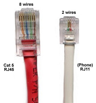
Cable Modem With Either Airport Extreme Or Time Capsule Macrumors.
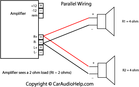
Car Audio Parallel Speaker Wiring Diagram.

Rj 11 4 Pair Phone Wiring Color Codes And Diagram Circuit Schematic.
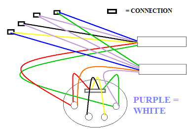
Telephone Wiring And One Jack Not Working Ask Me Help Desk.

Uk Telephone Wiring.

Get More Information Regarding The Home Phone Wiring Diagram Using.

Data Telephone Wiring Standards.

Lju 2 3a Telephone Extension Socket Telephone Wiring.

Telephone Socket Wiring Diagram.
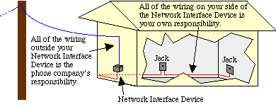
Doing Your Own Telephone Wiring.
Wiring Diagram Generator Voltage Regulatorwiring Diagram

304 330 334 336 342 344 346 452 367 368 391 392.

Wire Harness Used For Car Lamp Hid 1007 Oem Number Hid 1007.

Http Www Vehicle Wiring Products E Hoto Dig05 Jpg.
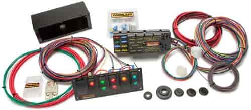
Products 50005 Painless 8 Circuit Race Car Wire Harness Kit.

Automotive Wire Harness Products From China Mainland Buy Automotive.

Vehicle Wiring Products Men Da Aer Det Bara Motorel Egentligen.

Wire Car Repair Tools Auto Repair Tools Windshield Cut Out Wire Car.

Wiring Diagram 12v Generator To Voltage Regulator Wiring Diagram 12v.
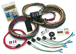
Performance Products 10123 Painless Muscle Car Wiring Harnesses.

Car Amplifier Repair Car Amplifier Brand Model Number In Tomcatso.
Simple Flasher circuit diagram
Most of you asked about a LED flasher circuit.Here it is.Here I have used famous IC LM3909.This circuit operates with 1.5V

Read Full article[...]

12V to DC 300V 55 mA
This circuit can generate 300v from 12V power supply.This circuit operates with common transistors 2N3055 and 2N1305.This circuit can provide 55mA current.you can get fun with this

Note
# Be careful when you operate this circuit
# Build this circuit on a PCB
Read Full article[...]

Note
# Be careful when you operate this circuit
# Build this circuit on a PCB
BASIC ELECTRICAL CIRCUITS
This subcourse is designed to give you a basic knowledge of simple circuits that carry electricity from a power source to some kind of electrical equipment. With a knowledge of these fundamentals, you will be able to make better use of electrical equipment and to better understand future textual materials that mention electrical factors in the function of equipment.After completing the programmed text, you should be able to choose correct answers to questions about basic electrical circuits, current, resistance, amperes, volts, and equivalent.The series circuit below is an equivalent circuit because both circuits (do/do not) have the same E a and both circuits. Now that you know what happens to resistance and voltage in a parallel circuit, let us look at current.
Water Level Ditector Circuit
This is very useful circuit for us.Because by using this circuit you can control your water pump automatically.When the water goes down the trigger sensor level.The mot er will start automatically.After passing the threshold sensor level the mot er Will stop automatically.

Note
# When you fix sensors fix them tiddly.If not They will short together.
#This circuit works with 12V power supply.
Wireless Microphone circuit diagram
 Wireless Microphone circuit diagram
The ambit of frequencies for the FM advertisement bandage is 90MHz (MHz = Megahertz or 90 actor cycles per second). Because the FM microphone has a capricious acquainted circuit, it can be acquainted to a quiet atom on your bounded FM advertisement bandage for the best reception. When the baby microphone aspect is addled by sound, it converts the audio to a change in accepted through resistor R1 (see schematic diagram).
This electrical change is amplified and eventually abundance modulates the transmitter. The manual ambit of the FM microphone is about 100 feet, depending on the ability of the antenna (properly acquainted or not) and the affection of the FM radio receiver.
Vehicle Electrical System Demonstrator
 The ALD07 demonstrator is one in a range of self-contained fully operational auto electrical trainers designed for teaching basic electrical principles. Manufactured using original real vehicle components.
Full operation of headlights, side lights, brake lights indicators and alternator via a speed controller can be observed.
The following vehicle circuits and systems are included:
Starting
Charging
Ignition
Lighting
Light Wiring Problemford Mustang Forums

Meyer Snowplow Lights Parts And Accessories.

Wiring A Light Switch Power Into Light.
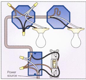
Lights With 2 Way Switch Wiring Diagram.

Wiring Diagram 3 If However You Want To Locate The.
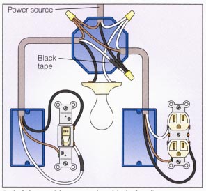
Light And Outlet 2 Way Switch Wiring Diagram.
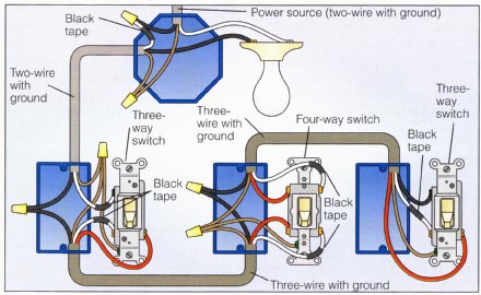
Power At Light 4 Way Switch Wiring Diagram.

Trailer Light Wiring Typical Trailer Light Wiring Diagram.

Typical 7 Way Trailer Wiring Diagram Circuit Schematic.

Way Switch With Lights Wiring Diagram.

Help With Fog Light Wiring Problem Ford Mustang Forums.
Brake Light Signal Module
Circuits of this kind are intended to drive LED Arrays in order to create more visibility and conspicuity when a vehicle is stopped or stopping. This circuit, in particular, will emit a visual alerting signal of 4 short flashes, followed by a steady on light that remains steady on as long as the brakes are applied.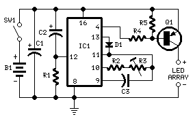
Parts:
R1_____________10K 1/4W Resistor
R2____________220K 1/4W Resistor
R3____________500K 1/2W Trimmer, Cermet or Carbon
R4______________1K8 1/4W Resistor (See Note)
R5______________1K8 1/4W Resistor
C1_____________47µF 25V Electrolytic Capacitor
C2______________1µF 25V Electrolytic Capacitor
C3_____________10nF 63V Polyester Capacitor
D1___________1N4148 75V 150mA Diode
IC1____________4060 14 stage ripple counter and oscillator IC
Q1____________BC327 45V 800mA PNP Transistor (See Note)
SW1____________SPST Brake Switch
B1______________12V Vehicle Battery
IC1 internal oscillator generates a square wave whose frequency is divided 64 times by the flip-flops contained in the chip in order to obtain about 1 to 4Hz at pin #4: this is the LED Array flashing frequency and can be set to the desired value by means of R3. A positive signal at D1 Cathode stops the oscillator after 5 pulses are counted. C2 and R1 automatically reset the IC whenever the brakes are applied. Q1 is the LED Array driver: LEDs will be on when pin #4 of IC1 goes low
Note:
* The transistor type suggested for Q1 will drive LED Arrays at currents up to 500mA. To drive Arrays requiring higher currents (up to 1A and even more) use a BD436 (32V 4A PNP Transistor) for Q1 and a 1K resistor for R4.
Read Full article[...]
Parts:
R1_____________10K 1/4W Resistor
R2____________220K 1/4W Resistor
R3____________500K 1/2W Trimmer, Cermet or Carbon
R4______________1K8 1/4W Resistor (See Note)
R5______________1K8 1/4W Resistor
C1_____________47µF 25V Electrolytic Capacitor
C2______________1µF 25V Electrolytic Capacitor
C3_____________10nF 63V Polyester Capacitor
D1___________1N4148 75V 150mA Diode
IC1____________4060 14 stage ripple counter and oscillator IC
Q1____________BC327 45V 800mA PNP Transistor (See Note)
SW1____________SPST Brake Switch
B1______________12V Vehicle Battery
IC1 internal oscillator generates a square wave whose frequency is divided 64 times by the flip-flops contained in the chip in order to obtain about 1 to 4Hz at pin #4: this is the LED Array flashing frequency and can be set to the desired value by means of R3. A positive signal at D1 Cathode stops the oscillator after 5 pulses are counted. C2 and R1 automatically reset the IC whenever the brakes are applied. Q1 is the LED Array driver: LEDs will be on when pin #4 of IC1 goes low
Note:
* The transistor type suggested for Q1 will drive LED Arrays at currents up to 500mA. To drive Arrays requiring higher currents (up to 1A and even more) use a BD436 (32V 4A PNP Transistor) for Q1 and a 1K resistor for R4.
Rain effect Generator
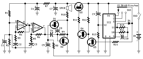
Sound effects generators trying to imitate rain sound or sea surf are well known to hobbyists from many years: their purpose is to induce relaxation and sleep or to help in concentration and study.The sound generated is restrained to a background level and these devices are frequently kept on the night table.Common designs use invariably Zener diodes or reverse-biased transistors base-emitter junctions as white noise generators. The main snag of these circuits is that a supply of at least 12V is required, therefore a big battery pack or (more commonly) mains supply is used as power source.The aim of this project was to design a small, portable unit, powered by a 3V battery and capable of shutting-down after a preset delay, in order to save power.
Parts:
R1,R2,R13______10K 1/4W Resistors
R3,R5__________33K 1/4W Resistors
R4,R6___________1M 1/4W Resistors
R7____________100R 1/4W Resistor
R8____________330K 1/4W Resistor
R9____________100K 1/4W Resistor
R10____________47R 1/4W Resistor
R11_____________1K 1/4W Resistor
R12____________15K 1/4W Resistor
R14____________47K 1/4W Resistor
R15____________10M 1/4W Resistor
R16_____________1M8 1/4W Resistor
C1,C4,C7______100µF 25V Electrolytic Capacitors
C2,C3,C6______100nF 63V Polyester or Ceramic Capacitors
C8,C10________100nF 63V Polyester or Ceramic Capacitors
C5_____________47µF 25V Electrolytic Capacitor
C9_____________10µF 63V Electrolytic Capacitor
D1___________1N4148 75V 150mA Diode
Q1___________2N3819 General-purpose N-Channel FET
Q2____________BC337 45V 800mA NPN Transistor
Q3____________BC327 45V 800mA PNP Transistor
Q4,Q5_________BC547 45V 100mA NPN Transistors
IC1___________TL062 Low current BIFET Dual Op-Amp
IC2____________4060 14 stage ripple counter and oscillator IC (See Notes)
SW1____________1 pole 3 ways Rotary Switch
SW2____________SPST Slider Switch
SPKR___________8 Ohm Loudspeaker (40 to 85mm. diameter)
B1_____________3V Battery (two AA or AAA cells wired in series etc.)
Two BIFET Op-Amps are used as a good, low voltage supply, very low current, white noise source. A sound resembling to a rain shower is reproduced by the speaker after being amplified by Q2.
The higher part of the white noise spectrum is attenuated by C8, slowly driven into operation by means of Fet Q1 acting as a variable resistor. Therefore, a sort of automatic tone control is obtained.
IC2 provides all the timings: it auto-resets at switch-on, shutting-down the generator after one of three time-delays, chosen by means of SW1. It provides also, through R8, slow charge and discharge of C5, in order to change smoothly high-frequency attenuation. Q3 is used as a dc switch for the generator circuit. Q4 and Q5 are its drivers.
Notes:
* Different operating delays can be chosen by changing R16 and/or C10 value.
* 4060 ICs by some manufacturers are unable to oscillate at 3V supply. Motorolas MC14060 is therefore highly recommended for IC2.
* If a fixed operating delay is desired, SW1 can be omitted and R14 and D1 anode can be hard wired to the proper pin of IC1.
* Output volume can be increased lowering R9 value to about 47K. On the other hand it can be reduced increasing R9 value to about 150K.
* If variable high-frequency attenuation is not needed, C5, C8, Q1 and R8 may be omitted.
* If auto shut-down is not needed, omit R11, R12, R13, R14, Q3, Q4, Q5, C9, D1 and SW1, connecting pin #12 of IC2 to negative ground.
* If only a straightforward white noise generator is required, omit also IC2, R15, R16 and C10 besides the above listed parts.
* Current consumption is about 7mA and less than 600µA when in stand-by mode.
* After shut-down, the circuit can be restarted opening SW2, then closing it again.
Disclaimer: we cant claim or prove any therapeutic effectiveness for this device.
Read Full article[...]
Parts:
R1,R2,R13______10K 1/4W Resistors
R3,R5__________33K 1/4W Resistors
R4,R6___________1M 1/4W Resistors
R7____________100R 1/4W Resistor
R8____________330K 1/4W Resistor
R9____________100K 1/4W Resistor
R10____________47R 1/4W Resistor
R11_____________1K 1/4W Resistor
R12____________15K 1/4W Resistor
R14____________47K 1/4W Resistor
R15____________10M 1/4W Resistor
R16_____________1M8 1/4W Resistor
C1,C4,C7______100µF 25V Electrolytic Capacitors
C2,C3,C6______100nF 63V Polyester or Ceramic Capacitors
C8,C10________100nF 63V Polyester or Ceramic Capacitors
C5_____________47µF 25V Electrolytic Capacitor
C9_____________10µF 63V Electrolytic Capacitor
D1___________1N4148 75V 150mA Diode
Q1___________2N3819 General-purpose N-Channel FET
Q2____________BC337 45V 800mA NPN Transistor
Q3____________BC327 45V 800mA PNP Transistor
Q4,Q5_________BC547 45V 100mA NPN Transistors
IC1___________TL062 Low current BIFET Dual Op-Amp
IC2____________4060 14 stage ripple counter and oscillator IC (See Notes)
SW1____________1 pole 3 ways Rotary Switch
SW2____________SPST Slider Switch
SPKR___________8 Ohm Loudspeaker (40 to 85mm. diameter)
B1_____________3V Battery (two AA or AAA cells wired in series etc.)
Two BIFET Op-Amps are used as a good, low voltage supply, very low current, white noise source. A sound resembling to a rain shower is reproduced by the speaker after being amplified by Q2.
The higher part of the white noise spectrum is attenuated by C8, slowly driven into operation by means of Fet Q1 acting as a variable resistor. Therefore, a sort of automatic tone control is obtained.
IC2 provides all the timings: it auto-resets at switch-on, shutting-down the generator after one of three time-delays, chosen by means of SW1. It provides also, through R8, slow charge and discharge of C5, in order to change smoothly high-frequency attenuation. Q3 is used as a dc switch for the generator circuit. Q4 and Q5 are its drivers.
Notes:
* Different operating delays can be chosen by changing R16 and/or C10 value.
* 4060 ICs by some manufacturers are unable to oscillate at 3V supply. Motorolas MC14060 is therefore highly recommended for IC2.
* If a fixed operating delay is desired, SW1 can be omitted and R14 and D1 anode can be hard wired to the proper pin of IC1.
* Output volume can be increased lowering R9 value to about 47K. On the other hand it can be reduced increasing R9 value to about 150K.
* If variable high-frequency attenuation is not needed, C5, C8, Q1 and R8 may be omitted.
* If auto shut-down is not needed, omit R11, R12, R13, R14, Q3, Q4, Q5, C9, D1 and SW1, connecting pin #12 of IC2 to negative ground.
* If only a straightforward white noise generator is required, omit also IC2, R15, R16 and C10 besides the above listed parts.
* Current consumption is about 7mA and less than 600µA when in stand-by mode.
* After shut-down, the circuit can be restarted opening SW2, then closing it again.
Disclaimer: we cant claim or prove any therapeutic effectiveness for this device.
Advanced Linear NiMH NiCd Fast Battery Charger
This is a simple Batteries charger for NiMH/NiCd.It Requires No Microcontroller or any Firmware.Linear Technology Corporation introduces the LTC4060, an autonomous 1- to 4-cell, 0.4A to 2A linear NiMH and NiCd battery charger. The LTC4060 includes all the functions required for a battery charger circuit, operating without the aid of a microcontroller or firmware. The design is simple and needs only three passive components. The LTC4060 also eliminates the need for a sense resistor and blocking diode, which increases efficiency and lowers the solution cost. This IC is targeted at applications including portable medical equipment, automotive diagnostic systems and industrial/telecom test devices.
Features
- Complete Fast Charger Controller for Single, 2-, 3- or 4-Series Cell NiMH/NiCd Batteries
- No Firmware or Microcontroller Required
- Termination by –?V, Maximum Voltage or Maximum Time
- No Sense Resistor or Blocking Diode Required
- Automatic Recharge Keeps Batteries Charged
- Programmable Fast Charge Current: 0.4A to 2A
- Accurate Charge Current: ?5% at 2A
- Fast Charge Current Programmable Beyond 2A with External Sense Resistor
- Automatic Detection of Battery
- Precharge for Heavily Discharged Batteries
- Optional Temperature Qualified Charging
- Charge and AC Present Status Outputs Can Drive LED
- Automatic Sleep Mode with Input Supply Removal
- Negligible Battery Drain in Sleep Mode: <1?A
- Manual Shutdown
- Input Supply Range: 4.5V to 10V
Subscribe to:
Comments (Atom)
