Showing posts with label with. Show all posts

Alarm Clock With Day Selector

This  circuit disables an alarm clock on Saturdays and Sundays when people like to sleep in but enables normal operation on Mondays to Fridays so that people rise in time for work or school. The core of the circuit is a 4017 decade counter which acts as the day counter and it is used in conjunction with a desk clock which acts the alarm and a watch module with alarm function which provides one clock pulse very day to the 4017. In operation, the watch module feeds a day pulse via transistor Q3 to the clock input of IC1. This has seven outputs connected via day switches (S1-S7) and diodes D3-D9 to Q1 which disables the alarm signal to the speaker via transistor Q2. LEDs1-7 indicate the actual day (if you forget!).

Circuit diagram:

Alarm-clock-with-day Selector Circuit Diagram

Alarm Clock With Day Selector Circuit Diagram

To set the system, set the desk clock for the correct time and for the desired alarm time (eg, 6’o’clock). The watch module is set to the correct time and its alarm set to midnight. The day counter, IC1, is set to the correct day, as indicated by the LEDs, by pushing switch S12 and closing switch S8 or S9. S8 is normally left open to conserve the battery by leaving the LEDs off. As shown on the circuit, switches S1-S7 are set to sound the alarm on Mondays to Fridays and disable it on Saturday and Sunday. However, you can change the days to suit your work habits.

Author: Rasim Kucalovic - Copyright: Silicon Chip Electronics

Read Full article[...]

555 Timer With Variable On Off Times

This circuit enables the on/off times of a 555 timer to be independently varied over a wide range. This is not possible with a conventional 555 circuit with the RC network being charged from the positive supply rail and discharged via pin 7. Instead, the capacitor at pins 2 & 6 of IC1 is charged and discharged from the output at pin 3. Furthermore, the charging and discharging circuits are different, being isolated by diodes D1 & D2.

555 Timer Circuit With Variable On/Off Times circuit schematic

Therefore the capacitor at pins 2 & 6 is charged via diode D2 and trimpot VR2 and discharged via D1 and trimpot VR1. With this arrangement you can have very long on times combined with very short off times and vice versa, or you can adjust the duty cycle to exactly 50% and so on. This circuit also employs a second 555 timer (IC2) as an inverter so that complementary pulses are available, if required. If not, delete IC2.
Read Full article[...]

Stereo Amplifier with Voltage Regulators

A simple stereo audio amplifier is built around two 7905 negative-voltage regulators (IC1 and IC2) and a few discrete components. The circuit will also work with other 79XX regulators if appropriate power supply is used. Regulator IC 7905 works as an amplifier for the voltages applied to common pin2 (Ground or GND). Also check the LM317 audio amplifier, another interesting circuit.
The minimal voltage drop over the standard 7905 is around 2V and it depends on the output current. Feedback resistors in the IC set the gain of the channel internally. The amplifier is a class-A audio amplifier. The minimal applicable value of R3 for the regulator 7905 is 8.2 to 10 ohms per 5W.

1W Stereo Amplifier with Voltage Regulators Circuit Diagram

A simple Stereo Amplifier with Voltage Regulators

If the required output current for LS1 is below 100 mA, the value of resistor R3 can be 33 to 51 ohms per watt. The circuit works with any load resistance (R3 in parallel with LS1 as the load) under the condition that the regulator is not overloaded with current and power dissipation. However, it is preferable to use a loudspeaker with a high resistance (8 ohms, 16 ohms or more). The amplifier works well with low-impedance headphones having a resistance of 24 to 32 ohms. The voltage difference between the ground pin of 7905 and the output pin is fixed internally.
S2 is the on/off switch. Switch S1 is for mono/stereo selection. When switch S1 is closed, the amplifier works as a two-way mono amplifier. If S1 is open, the amplifier works as a stereo amplifier. If no input signal is applied, the DC voltage on the output of the regulator 7905 should be around –5V, which depends to some extent on the value of VR1. The maximum output current of 7905 can be up to 1A and the maximum power dissipation is up to 15W. Mount the regulator IC 7905 on a heat-sink with thermal resistance below 15°C/W.
Source:  http://www.ecircuitslab.com/2012/08/a-simple-stereo-amplifier-with-voltage.html
Read Full article[...]

Cross Linking With Two Patch Cables

In networks, the supremacy of coax cable is a thing of the past. Nowadays, Ethernet connections are made using UTP cables. The BNC plug has yielded to the 8-way RJ45 plug. Previously, coax cables were daisy-chained from computer to computer and terminated at the two ends using 50-_ resistors, but modern networks use central ‘socket boxes’ (switches and/or hubs) to interconnect everything. The connections between the hubs and the computers are made using patch cables having the same sequence of leads in the RJ45 connectors at each end. For making a direct connection between two computers without using a hub or switch, a ‘crossover cable’ is used.

Cross-Linking With Two Patch Cables
Cross-Linking With Two Patch CablesSuch a cable has the leads cross-linked in order to allow the two computers to directly communicate with each other. If there are problems with the network, it can be handy to be able to directly interconnect twocomputers, or directly connect a computer to a cable or ADSL modem without using a hub or switch. A long crossover cable is not always available, and shoving around computers is not an attractive alternative. Consequently, we can use a dual RJ45 wall outlet box to construct an adapter, which can be used to interconnect the two patch cables coming from the equipment in question. This outlet box must be wired to create a cross-linked connection. This is done by making the following internal connections:
  • 1 → 3
  • 2 → 6
  • 3 → 1
  • 4 → 4
  • 5 → 5
  • 6 → 2
  • 7 → 7
  • 8 → 8
 
Source by : streampowers
Read Full article[...]

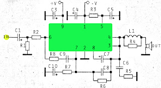
60W ICs amplifier with OM961

Amplifier circuit is very suitable for use in car audio speakers that use a subwoofer, with a power output of about 60W and impedance of 4 Ohm. Supply voltage ranging from 12V to 35 volts with currents +, -, and ground. If using battery then use 12V DC to DC converter which produces 3 voltage +, -, and ground.
60Watt ICs amplifier with OM931

Component List :
Resistor
R1 = 10K
R2 = 4K7
R3 = 10R
R4 = 2.2R
R5 = 10R
R6 = 10K
R7 = 680R
R8 = 300R
Capacitor
C1 = 1uF
C3 = 10uF
C4 = 10uF
C5 = 470uF
C6 = 0.1uF
C7 = 100uF
C8 = 120pF
C9 = 270pF
C10 = 47uF
IC = OM931 , OM961
Read Full article[...]